
When web tension control systems for converting prevent material waste
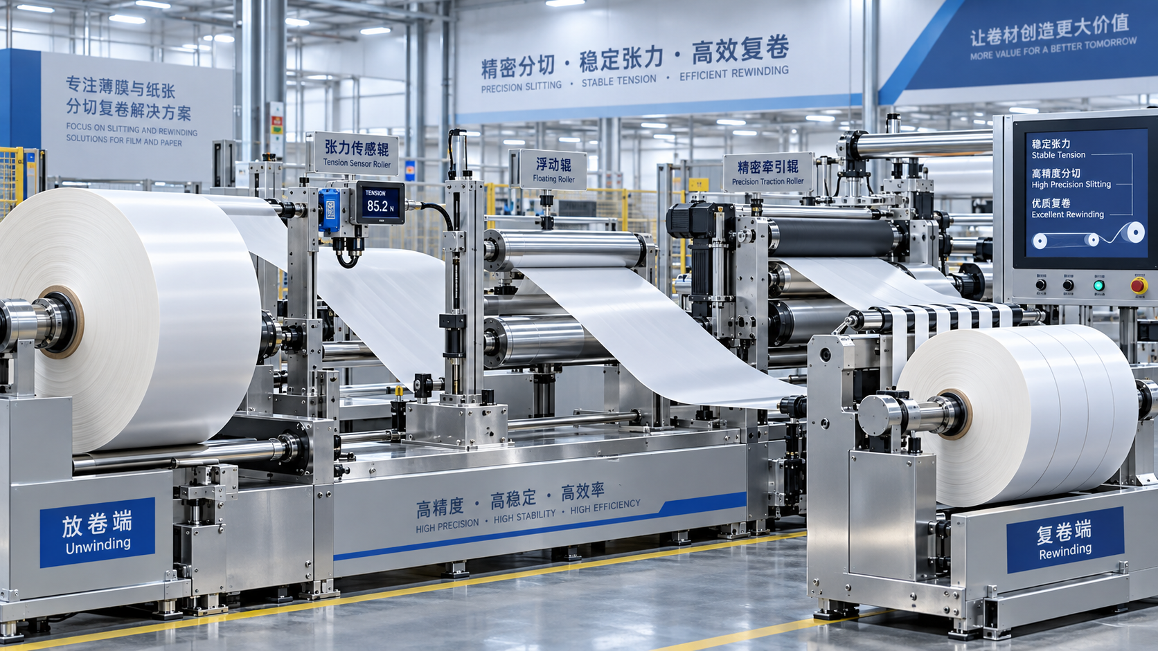
Material waste often begins before a web breaks. A roll can remain intact while unstable tension creates register drift, wrinkles, telescoped rewinds, uneven coating weight, distorted die-cut geometry, or an unacceptable curl profile. The resulting rejected material may appear downstream, yet the source is frequently an earlier tension disturbance that was never measured, isolated, or corrected fast enough.
Web tension control systems for converting prevent this loss by keeping the longitudinal force in the moving substrate within a usable range as roll diameter, line speed, material stiffness, and process resistance change. The useful range is not simply the highest tension a web can survive. It is the narrow operating window that maintains tracking, traction, dimensional stability, and process contact without stretching, crushing, marking, or breaking the material.
A sound system therefore has to respond to the real behavior of the line rather than hold one arbitrary setpoint. Unwinding, printing, laminating, coating, slitting, die-cutting, embossing, folding, and rewinding all introduce different disturbances. A tension arrangement that appears stable while running a uniform paper grade at a fixed speed can produce avoidable scrap during acceleration, roll changes, or a switch to a lighter, moisture-sensitive substrate.
Waste is usually created at transition points
Steady-state running can conceal weaknesses in a control design. The material loss that matters most commonly appears when the machine changes state: the drive ramps up, a brake releases, a splice passes through a sensing zone, a dancer reaches its travel limit, or a downstream station briefly draws more web than expected. These events turn stored mechanical energy and control delay into temporary tension excursions.
At an unwind, effective roll radius decreases continuously. If braking torque stays fixed, web tension rises as the roll becomes smaller. If a controller estimates diameter poorly, a roll may run acceptably at the outside diameter and become over-tensioned later in the run. Conversely, insufficient torque near the core permits slack web, poor edge control, and wrinkles that may be carried into a print or lamination nip.
At a rewind, the relationship reverses. The winding roll gains diameter and inertia, so torque demand changes throughout the job. A rewind that only follows motor speed can form a loose pack at one point in the roll and excessive interlayer pressure at another. Both conditions can turn usable product into downgraded material, especially where roll hardness, slit-edge quality, or later unwinding behavior is part of product acceptance.
Speed changes expose a separate issue: tension control needs enough authority to correct quickly, but not so much gain that the system hunts. A fast, high-gain response can cause repeated tension peaks around the target. A slow response lets a disturbance travel through multiple sections before correction. Neither issue is solved by selecting a stronger brake or larger motor alone; the control loop, sensor signal, web path, drive dynamics, and inertia all determine the response.
Separate the web into tension zones before selecting hardware
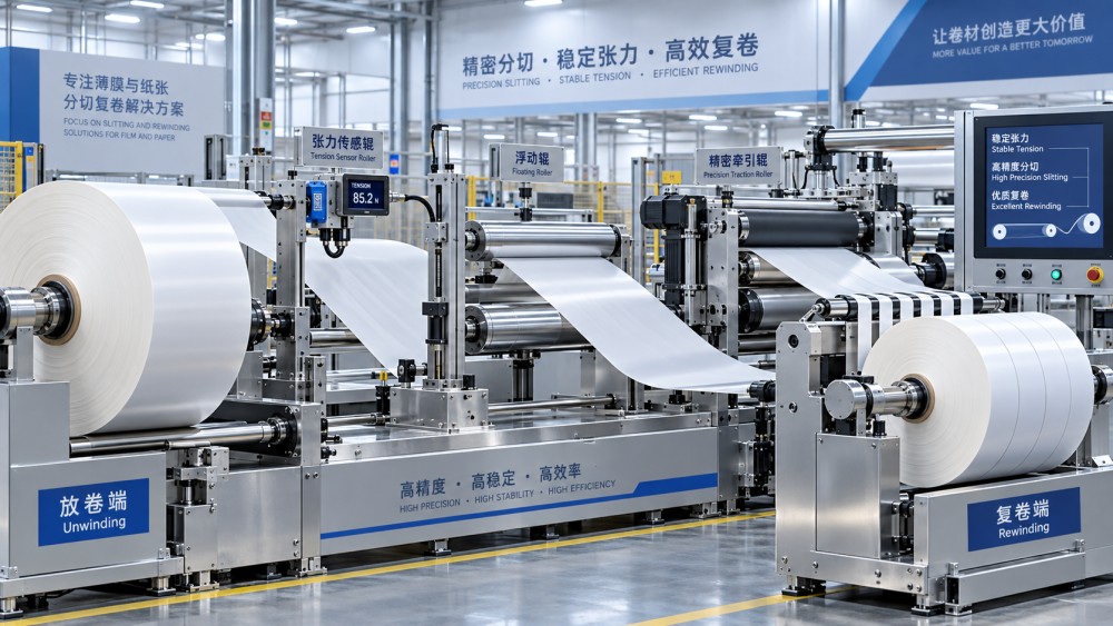
Long converting lines should not be treated as one continuous tension problem. Each driven or traction-controlled section establishes a tension zone. A pull roll, draw roll, nip, or driven process station isolates the force behavior on one side from the next. Without clear zone boundaries, a change in one station can propagate across the machine and make fault diagnosis difficult.
For example, a digital print section may require a stable low-tension zone to preserve image registration and avoid substrate distortion. A laminating nip needs controlled traction through the bonding area, while its unwind and rewind sections must accommodate changing roll diameters. A slitter may require enough tension to keep cuts clean and maintain web separation, but excessive force can damage thin films, tear weak paper edges, or magnify a defect introduced by an upstream roll.
Zone design should follow the process, not a generic machine layout. Questions that reveal the correct boundaries include:
- Which station changes web speed or applies a pulling force independent of adjacent sections?
- Where does process contact require a stable web condition, such as a print cylinder, coating head, laminating nip, die-cutting station, or embossing point?
- Which locations can accumulate web length through a dancer, accumulator, or free loop during a splice or temporary speed mismatch?
- Where would a short tension spike create an irreversible defect rather than a recoverable tracking variation?
A dancer is useful when the line needs stored web length and mechanical isolation, particularly around intermittent downstream demand or roll-change events. It also provides position feedback that can reveal a developing mismatch between sections. Yet a dancer is not automatically the best sensor for every zone. Its mass, friction, pneumatic behavior, and travel range affect its response. A lightly loaded dancer may be sensitive but unstable; a heavily loaded dancer may smooth disturbances while failing to react before a delicate web is damaged.
Load cells measure actual web force through a roller structure and are often preferred where the process demands direct tension feedback. Their value depends on correct mechanical installation. The web wrap angle, roller geometry, bearing condition, load-cell alignment, and frame stiffness influence the signal. A signal that appears noisy may result from roller vibration or an incorrect force path, not from a deficient controller.
Setpoints must reflect material behavior, not only roll width
Tension is often expressed as total force or force per unit width. Neither figure is meaningful in isolation. A wide, strong board liner and a narrow, extensible film can show the same total tension while facing very different stress conditions. Basis weight, caliper, fiber orientation, coating structure, moisture content, perforation pattern, splice design, and previous winding history all alter the safe operating range.
Paper and board grades deserve particular care because their apparent stiffness can change during a run. Moisture variation affects dimensional response and tensile behavior. A web that is flat at the unwind may develop edge waviness after exposure to heat, water-based coating, steam, or differential drying. Raising tension to suppress the visible wave may temporarily improve tracking while increasing the likelihood of web breaks or permanent stretch. The better response is to determine whether the defect originates from moisture profile, roll hardness, guiding, nip pressure, or tension imbalance.
Films and laminates add another constraint. An elastic web can tolerate a temporary load without breaking, yet still retain elongation that later appears as register error, curl, or a poor winding profile. Metallized, coated, and heat-sensitive substrates may be marked by localized contact pressure even where average tension is within target. The tension setpoint must therefore be assessed with process temperature, nip configuration, and dwell time rather than tensile strength alone.
For slit rolls, total unwind tension is only part of the answer. The slit width, knife method, differential rewind arrangement, and core engagement determine whether each lane receives appropriate winding force. A broad parent roll may look stable on the main tension display while narrow lanes build unevenly because friction, differential shaft settings, or air entrainment differs across the web.
Control architecture should match the disturbance
Closed-loop tension control usually combines a measured variable, a controller, and an actuator. The measured variable may be load-cell force, dancer position, motor torque, or a calculated value based on drive behavior. The actuator can be a pneumatic brake, regenerative brake, motor drive, clutch, or a coordinated speed command to a draw roll.
Torque control is useful when motor characteristics and roll diameter are well known, but it is an indirect estimate of web force. Friction changes, mechanical losses, core slip, and roll-density variation can make a torque-derived value diverge from actual tension. It is better suited to applications with repeatable mechanics or as part of a broader control strategy than as proof that the web is receiving the intended force.
Load-cell feedback directly observes tension, but it does not remove the need for sensible speed coordination. If adjacent drives fight each other, the load-cell loop will constantly correct a disturbance created by the machine itself. Coordinated drives need defined master speed logic, appropriate ramp profiles, and limits that prevent one station from demanding an impossible response from another.
Dancer-position control is especially effective where buffering matters. The dancer position becomes the controlled variable, and web tension is generated through the dancer loading arrangement. This approach is vulnerable when the available travel is too short for the largest expected transient. Once the dancer reaches an end stop, its buffering benefit disappears and the line may see an abrupt tension event. Splice timing, acceleration limits, and roll-change sequencing must be designed around available storage length.
Splices need their own control logic
A splice is not merely a thicker section of web. It can change local stiffness, thickness, surface friction, tensile strength, and the way the material passes a nip or sensing roller. The event may also coincide with an unwind transfer, brake change, or accumulator movement. Treating every splice as a normal run condition invites a tension excursion precisely when the material is least uniform.
Splice detection should be tied to a defined response: limited acceleration, a temporary control mode, adjusted tension targets where justified by the process, or a controlled speed window through sensitive stations. The response must be short and deliberate. Broadly lowering tension for an extended period can create slack, poor register, or loose winding that causes more waste than the splice itself.
Adhesive tape and overlap geometry also matter. A splice that passes cleanly through one roller path may lift at a sharp wrap angle or stall momentarily at a narrow nip. The web path should be reviewed with the actual splice construction, including maximum tape thickness and edge condition, rather than with a bare substrate sample.
Commissioning should be based on traces, not impressions
A stable-looking web is not sufficient evidence of control quality. Commissioning should capture tension, dancer position where used, line speed, actuator output, and relevant drive commands through the full operating sequence. The most revealing record includes thread-up, acceleration, deceleration, steady operation, splice passage, roll transfer, and emergency stop recovery.
Start with mechanical checks. Confirm roller alignment, bearing condition, web wraps, load-cell orientation, brake integrity, drive direction, and sensor zero. A controller cannot compensate reliably for a roller that drags intermittently or a load cell carrying unintended side load. Establishing a valid zero with the web removed and verifying signal direction with a known force prevents a basic error from becoming a prolonged tuning exercise.
Then tune the loop against representative materials and roll builds. A controller adjusted on a full, uniform roll may behave differently near the core or with a soft-wound roll. Record the setpoint, actual force, transient peak, settling behavior, and the associated material condition. The aim is not to chase an immobile signal; normal process variation exists. The aim is to prevent excursions that create defects, breaks, or unstable downstream processing.
Alarm limits deserve the same attention as the nominal target. Limits that are too wide merely document loss after it has occurred. Limits that are too narrow create frequent nuisance events and may encourage alarm bypassing. Separate warning behavior from protective action where the process permits it, and use delay logic carefully so brief, harmless disturbances do not mask a sustained loss of control.
Maintenance preserves waste reduction after installation
Tension performance changes as equipment ages. Brake friction surfaces wear, pneumatic regulators drift, dancer pivots gain resistance, rollers collect coating or adhesive, and load-cell cables suffer damage near moving assemblies. These changes often appear first as an increase in correction activity, a slower recovery after speed changes, or unexplained differences between comparable jobs.
Routine verification should include sensor zero and span checks, inspection of roller rotation, confirmation of dancer free movement, examination of pneumatic supply quality, and review of stored tension trends. When a process begins producing more breaks or rewind defects, compare current traces with a known stable run before changing setpoints. A higher target may hide slack caused by a weak actuator, while a lower target may conceal a sticking dancer until the next speed transition.
Material waste falls when tension is treated as a controlled process condition with known limits, distinct zones, valid feedback, and documented behavior during transitions. The practical result is fewer defects that must be cut out, rewound, reprinted, relaminated, or discarded after the line has already consumed material and production time.
Industry Briefing
Get the top 5 industry headlines delivered to your inbox every morning.
Recommended News