
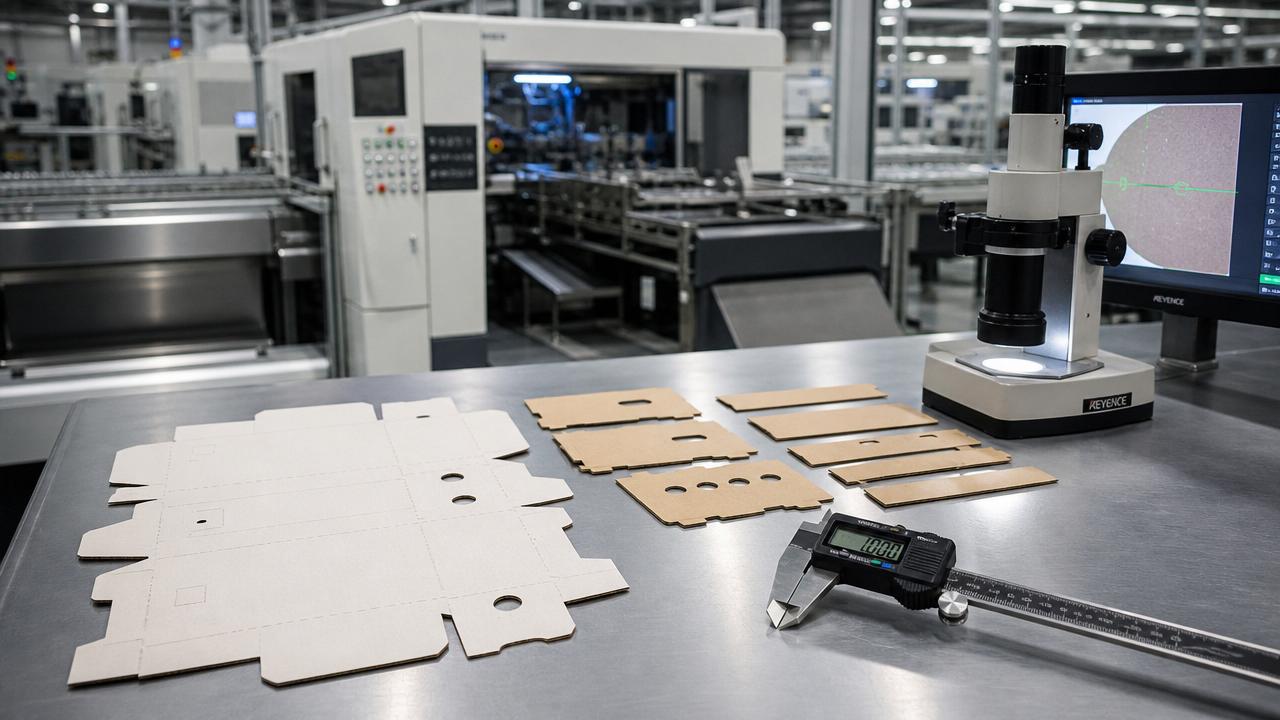
In precision die cutting, the difference between a stable production run and costly scrap often comes down to tolerances that are too small to see.
For technical evaluators, the real question is not whether a supplier can cut a shape, but whether it can hold capability at speed.
Dimensional accuracy, registration, creasing, material behavior, and downstream repeatability all determine whether a die-cut component performs reliably in production.
This guide focuses on the tolerance checkpoints that matter when evaluating equipment, tooling, sample reports, or a converting supplier’s process capability.
Start with the Function, Not the Drawing
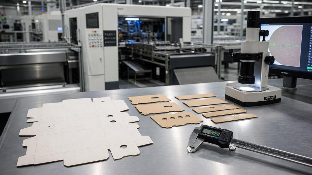
The most important tolerance is the one that protects product function. A visually acceptable part may still fail folding, sealing, assembly, or automated feeding.
Technical evaluators should classify each feature by consequence. Critical features control fit, registration, barrier integrity, sealing surfaces, or mechanical lock performance.
Secondary features influence appearance, handling, or brand presentation. Noncritical edges may tolerate wider variation without affecting performance or downstream automation.
This hierarchy prevents over-specification. Tight tolerances everywhere increase tooling cost, slow troubleshooting, and create unnecessary rejection risk during production approval.
For packaging, cartons, labels, gaskets, or paper-based components, tolerance review should always connect dimensions with actual use conditions and converting sequence.
Dimensional Tolerances: Length, Width, and Profile Accuracy
Basic dimensional tolerance covers the finished outside size, internal cutouts, slots, tabs, windows, and profile contours after die cutting.
In precision die cutting, these dimensions are affected by die wear, press stability, sheet movement, web tension, and material compressibility.
Evaluators should verify both absolute dimensions and profile consistency. A part can meet length tolerance while showing distorted corners or uneven radii.
For flatbed systems, check repeatability across the sheet, especially between lead edge, center, and tail edge positions under production speed.
For rotary die cutting, confirm accuracy along the web direction and across the web, because cylinder runout and tension variation appear differently.
Recommended checks include first article measurement, multi-cavity comparison, edge-to-edge repeatability, and capability sampling after warm-up rather than only at setup.
Ask whether the stated tolerance applies to a single sample, a short run, or continuous production under normal substrate and speed conditions.
Registration Tolerance: Where Cutting Meets Printing, Creasing, and Coating
Registration tolerance defines how accurately the die-cut geometry aligns with printed graphics, embossed areas, coatings, foil, creases, or laminated layers.
This is often more important than raw dimensional tolerance in printed packaging, display cartons, labels, and digitally personalized short-run production.
Misregistration may expose white edges, cut into artwork, shift glue flaps, or weaken locking features even when dimensions look acceptable.
Evaluators should review machine registration systems, camera guidance, sheet alignment, web control, gripper accuracy, and compensation for print distortion.
Digital print workflows require special attention because variable data, ink laydown, drying, and substrate movement can influence cut-to-print accuracy.
For corrugated board, registration must account for board warp, flute direction, caliper variation, and compression during feeding and die impression.
A practical approval process should include registration targets, tolerance bands, production-speed samples, and inspection under actual artwork rather than blank material only.
Crease and Score Tolerances: The Hidden Driver of Fold Quality
In paperboard and corrugated applications, crease accuracy often decides whether a box folds squarely, glues cleanly, and runs through automation.
Crease position tolerance should be evaluated relative to adjacent cuts, fold lines, glue panels, locking tabs, and product-contact areas.
A crease that shifts slightly may create skewed cartons, cracked print, uneven compression, or resistance in high-speed folder gluer sections.
Technical evaluators should check crease width, depth, bead symmetry, channel selection, rule height, matrix placement, and board recovery after scoring.
Material grain direction also matters. A crease across the grain behaves differently from a crease with the grain, especially on coated boards.
For corrugated board, flute crush must be monitored. Excessive impression can weaken stacking strength, while insufficient scoring causes spring-back and poor folding.
Samples should be folded after conditioning and, where possible, tested on downstream equipment instead of judged only by static bench inspection.
Cut Edge Quality: Burrs, Dust, Nicks, and Fiber Pull
Precision is not only about measured location. Edge quality affects appearance, hygiene, sealing performance, adhesive bonding, and equipment cleanliness.
Paper-based materials may show fiber pull, angel hair, dusting, delamination, or crushed edges when tooling condition or impression pressure is wrong.
Films, foams, and laminated constructions may show burrs, rollover, adhesive smear, partial cutting, or layer separation after die cutting.
Evaluators should define acceptable edge condition using magnification, visual standards, particulate limits, or functional tests rather than vague descriptions.
Holding bridges and nicks should also be specified. They must retain parts during handling without leaving unacceptable tear marks after stripping.
In packaging operations, excessive dust can contaminate print surfaces, reduce glue performance, increase machine cleaning, and create quality complaints.
Ask suppliers how often tooling is inspected, how wear is detected, and whether edge quality trends are recorded during long production runs.
Material Tolerances: Caliper, Moisture, Compression, and Elastic Recovery
Many die-cutting problems are blamed on tooling when the root cause is material variation outside the expected processing window.
Caliper tolerance changes cutting pressure, crease depth, stripping reliability, and stack height. Small differences can become significant at industrial speeds.
Moisture content affects paper stiffness, curl, cracking, print registration, and dimensional stability before and after cutting or creasing.
Corrugated board introduces additional variation through flute profile, liner combination, bonding strength, warp, and localized compression from upstream handling.
Foams and elastomers require attention to compression set and elastic recovery. Parts may measure differently immediately after cutting and after relaxation.
Pressure-sensitive materials require liner release consistency, adhesive flow control, and clean kiss-cut depth to avoid liner strikes or poor weeding.
A strong evaluation includes incoming material specifications, conditioning rules, test timing, and measurement methods that reflect the real production environment.
Kiss-Cut, Through-Cut, and Depth Control Tolerances
Depth control becomes critical when the process must cut one layer while preserving another, as in labels, tapes, films, and adhesive laminates.
A kiss-cut that is too shallow causes poor matrix removal or incomplete release. Too deep, and it damages the liner or carrier.
Through-cut applications also need depth control because excessive penetration accelerates anvil wear, creates dust, and reduces dimensional consistency over time.
Evaluators should inspect liner marking, release force, peel behavior, matrix stripping, and cut completeness across the web or sheet.
Rotary systems should be checked for anvil condition, bearer pressure, cylinder concentricity, and thermal expansion during continuous operation.
Flatbed systems require attention to make-ready consistency, cutting plate condition, localized pressure compensation, and operator control of impression settings.
Depth tolerance should be validated with production materials, not substitute substrates, because adhesive thickness and compressibility strongly affect results.
Repeatability and Process Capability: Can It Hold Tolerance at Speed?
A sample part can be impressive, but technical evaluators need evidence that the process remains stable across the production run.
Repeatability should be measured across time, cavities, lanes, sheets, rolls, operators, and speed changes rather than from isolated golden samples.
Capability data helps distinguish a process centered within tolerance from one that passes inspection only by frequent adjustment or sorting.
Ask for Cp, Cpk, or equivalent statistical evidence when tolerances are critical, especially for automation-dependent packaging or functional components.
Measurement system analysis is equally important. If the inspection method has high variation, reported die-cutting accuracy may be misleading.
For high-speed post-press operations, evaluate start-up waste, adjustment frequency, tooling life, and tolerance drift during extended production windows.
Stable precision die cutting depends on the whole system: press rigidity, feeding, registration control, tooling, material, inspection, and operator discipline.
Tooling Tolerances: Die Construction, Rule Height, and Wear Control
Tooling converts the specification into physical reality, so its tolerances must be reviewed with the same seriousness as machine specifications.
Key factors include rule height, bevel type, rule hardness, rubber ejection profile, cavity spacing, and board or cylinder stability.
For complex cartons, stripping and blanking tools also influence whether tight features remain accurate after cutting and waste removal.
Laser-cut die boards, CNC-machined plates, and rotary dies each have different accuracy limits, maintenance needs, and cost-performance profiles.
Evaluators should ask how dies are certified, how tooling drawings are controlled, and whether wear limits are defined before production begins.
Tooling life should not be stated only in impressions. Material abrasiveness, coatings, recycled fiber content, and pressure settings can shorten usable life.
A reliable supplier will connect tolerance claims to die maintenance procedures, spare tooling strategy, documented change control, and clear requalification triggers.
Downstream Automation Tolerances: Feeding, Gluing, Sealing, and Assembly
The most expensive tolerance failures often appear after die cutting, when parts enter folder gluers, packing lines, applicators, or robotic assembly.
Small dimensional shifts can cause feeder mispicks, skewed folds, glue misplacement, open seams, sealing defects, or jams in high-speed automation.
For carton production, evaluate panel squareness, flap length, slot clearance, glue flap position, and final box geometry after folding.
For labels and adhesive components, review liner release, part spacing, edge lift, rewind tension, and applicator registration at operating speed.
For protective inserts or fiber-based components, check stackability, nesting consistency, and compression behavior under the actual packing sequence.
Approval should include a downstream trial whenever the die-cut part interacts with automated equipment, not only a dimensional inspection report.
This approach reduces hidden risk, because a technically “in tolerance” component may still be unsuitable for the process that consumes it.
How Technical Evaluators Should Structure a Tolerance Review
A disciplined review begins by separating critical-to-function features from cosmetic or low-risk dimensions, then matching inspection effort to consequence.
Next, confirm the tolerance basis. Determine whether values come from design needs, machine capability, legacy drawings, or unverified assumptions.
Request production-speed samples, not only setup samples. Include worst-case artwork, difficult substrates, tight cavities, and representative environmental conditions.
Define measurement tools clearly. Optical systems, calipers, pin gauges, vision inspection, peel tests, and functional fixtures serve different purposes.
Agree on sample size, sampling frequency, acceptance criteria, and response actions when trends move toward tolerance limits.
Review how the supplier controls change. New material lots, die repair, press transfer, operator changes, or speed increases may require revalidation.
Finally, connect tolerance approval with business risk. The strictest tolerance is not always best; the correct tolerance protects performance economically.
Common Warning Signs During Supplier or Equipment Evaluation
Be cautious when a supplier quotes tight tolerances without identifying material type, machine platform, inspection method, or production speed.
Another warning sign is reliance on visual approval for features that affect automated feeding, sealing, locking, or regulatory performance.
Unclear terminology can also create disputes. Cut tolerance, registration tolerance, crease tolerance, and finished assembly tolerance are not interchangeable.
If process capability is unavailable, ask for run data, inspection history, rejection rates, and examples from comparable applications.
For equipment purchases, be skeptical of catalog accuracy claims that do not specify substrate, format size, tooling type, and operating conditions.
Strong vendors usually discuss limits honestly. They explain trade-offs among speed, tolerance, material behavior, tooling cost, and maintenance frequency.
That transparency is often more valuable than an aggressive tolerance claim that cannot survive real production conditions.
Conclusion: The Right Tolerances Protect Performance and Yield
Precision die cutting should be evaluated as a controlled production system, not as a single cutting action or isolated sample dimension.
The key tolerances to check include dimensional accuracy, registration, crease position, edge quality, depth control, material behavior, and downstream compatibility.
For technical evaluators, the goal is to identify which variations create real risk and which specifications can remain commercially practical.
A supplier or machine that holds tolerance at speed, across materials, and through downstream processing delivers more value than one perfect sample.
When tolerance review is tied to function, capability data, and production reality, precision die cutting becomes a dependable foundation for industrial quality.